The following section guides the user through a typical data collection process. These steps may vary depending on the process your company uses.
Step 1: Setup Instrument
|
This is available when in MAP is in Engineer Mode. View Menu>Mode>Engineer |
.png "Important Information")
To set an instrument up:
| 1) | Connect the M.O.L.E. Profiler to the computer. Refer to the Communications Setup topic for your specific M.O.L.E. Profiler for more information. |
| 2) | Open the SelectiveRIDER® barrier box and connect the M.O.L.E. Profiler to the Connector Bridge. |
.png)
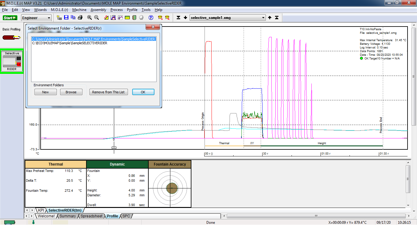
| 3) | Open an existing SelectiveRIDER® Environment Folder or create a new one. |
|
If the desired Environment is not displayed on the Environment Sidebar, the user can enable it from the Preferences dialog. File Menu>Preferences>Misc Tab. |
| 4) | On the M.O.L.E. menu, click Setup Instrument and the workflow wizard appears. |
|
When navigating through the wizard, the step list on the left uses a color key to inform the user of the current step, steps that have been completed and remaining steps.
|
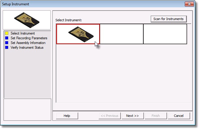
| 5) | Select the desired instrument from the dialog box. If there is none displayed, select the Scan for Instruments command button to detect all connected instruments. |
|
If the software does not detect a M.O.L.E. thermal profiler, using the communication cable connect it to the computer and click the Scan for Instruments command button to search again. M.O.L.E.® MAP software allows multiple instruments to be connected to a computer at one time. Selecting the Scan for Instruments command button will detect all instruments and display them in the dialog box. If no instrument is detected the software displays all of the Demonstration thermal profilers to select from. |
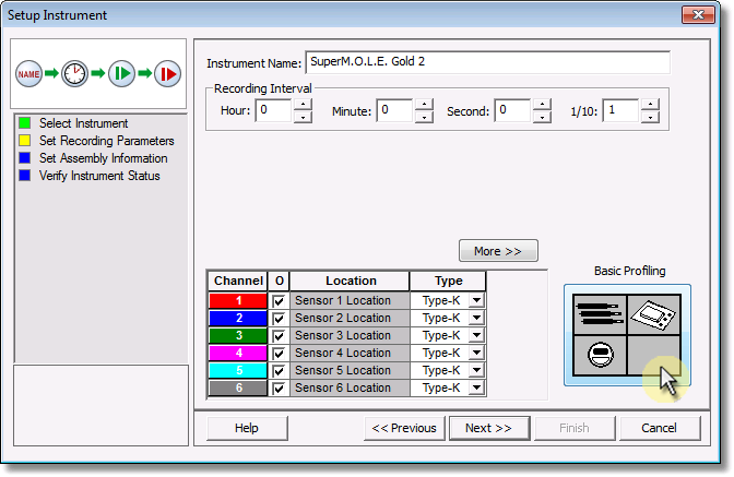
| 6) | Select the Next command button. |
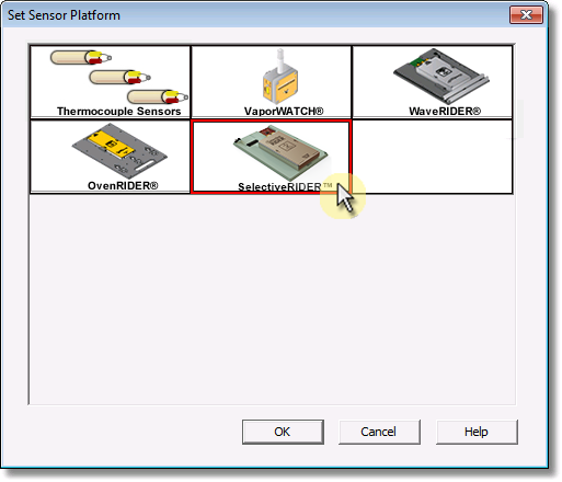
| 7) | Select the Sensor Platform button. |
|
For additional settings such as Start and Stop Parameters, select the More command button. Refer to topic Start and Stop Recording Parameters for detailed information for each setting. |
.png "Tip")
| 8) | Select the SelectiveRIDER® then the OK command button to proceed. |
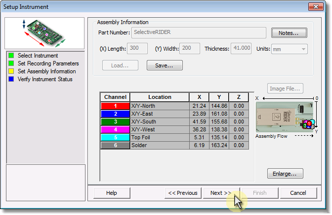
| 9) | Confirm the sensor selection and then select the Next command button. |
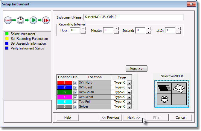
| 10) | Select the Next command button to send the settings to the instrument. |
| 11) | Verify the instrument status. This dialog box displays the health of the M.O.L.E. Profiler such as battery charge, internal temperature, thermocouple temperatures. If the user selects the Show Critical command button the dialog box will only display items that will prevent the user from completing a successful data run. |
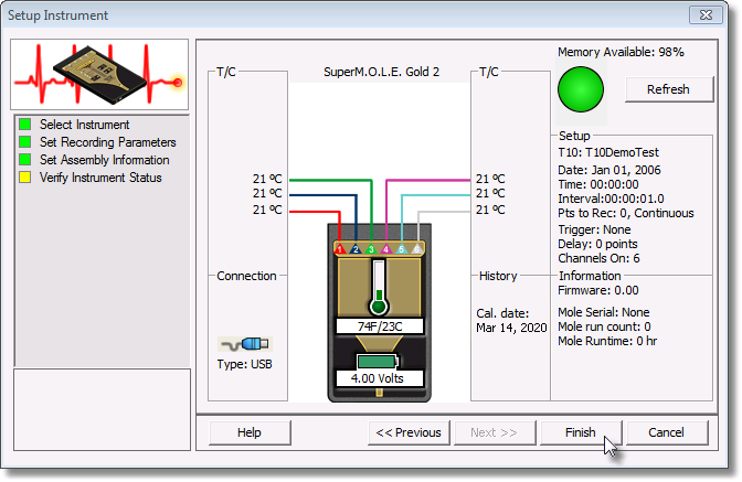
12) Select the Finish command button to complete the Setup Instrument wizard.
Step 2: Program Selective Machine
Use the following schedule to program the selective solder machine. Your selective solder program may vary in time, but MUST be in the following order. Any timing differences can be compensated for by altering the Machine Model after download using the MAP software. Timings may be longer between solder touches, but do NOT reduce the time.
|
Before programing, a photo or scanned image of the bottom side of the pallet can be used for the selective solder programming software. If you would like other formats use the provided links (internet connection required). |
.png)
.png)
.png)
.png)
.png)
Programming:
Mini Fluxometer® (Optional):
•Can be done before or after the selective solder schedule.
•V-Guage Test Mesh must be in the exact orientation in the pallet as shown. UP Test Mesh has no unique orientation.
•The center point (0,0) of the Mini Fluxometer™ Test Mesh from the pallet fiducal F1: X = 261.8mm (10.31") / Y=144.0mm (5.67").
.png)
|
DO NOT flux the Dynamic X/Y sensor |
.png "Warning")
•The two fiducials on the V-Gauge Test Mesh are 26.25mm (X & Y) from the center point (0,0).
.png)
V-Gauge Test Mesh Measurements:
Purge: Must run this pattern first. Program the nozzle to one or more of these holes to dispense this pattern to purge any air and prime the flux head. The purge pattern makes sure the nozzle is primed and ready for the other (perhaps more important) steps. If the first couple are missing or mis-shaped it indicates an issue with priming or blockage.
This example locates the hole closest to the 0,0. All of the holes in this pattern are equally spaced 4mm apart. Click to zoom |
|||
Flux Spray Start (From 0,0 Hole) |
X = -18mm Y = 8mm |
|
|
Flux Spray Hole #2 (From 0,0 Hole) |
X = -18mm Y = 12mm |
||
Flux Spray Hole #3 (From 0,0 Hole) |
X = -18mm Y = 16mm |
||
Flux Spray Hole #4 (From 0,0 Hole) |
X = -18mm Y = 20mm |
||
Flux Spray Hole #5 (From 0,0 Hole) |
X = -22mm Y = 20mm |
||
Flux Spray Hole #6 (From 0,0 Hole) |
X = -22mm Y = 16mm |
||
Flux Spray Hole #7 (From 0,0 Hole) |
X = -22mm Y = 12mm |
||
Flux Spray Hole #8 (From 0,0 Hole) |
X = -22mm Y = 8mm |
||
Flux Spray Hole #9 (From 0,0 Hole) |
X = -26mm Y = 8mm |
||
Flux Spray Hole #10 (From 0,0 Hole) |
X = -26mm Y = 12mm |
||
Flux Spray Hole #11 (From 0,0 Hole) |
X = -26mm Y = 16mm |
||
Flux Spray Hole #12 (From 0,0 Hole) |
X = -26mm Y = 20mm |
||
Flux Spray Hole #13 (From 0,0 Hole) |
X = -30mm Y = 20mm |
||
Flux Spray Hole #14 (From 0,0 Hole) |
X = -30mm Y = 16mm |
||
Flux Spray Hole #15 (From 0,0 Hole) |
X = -30mm Y = 12mm |
||
Flux Spray Hole #16 (From 0,0 Hole) |
X = -30mm Y = 8mm |
||
Flux Spray Hole #17 (From 0,0 Hole) |
X = -34mm Y = 8mm |
||
Flux Spray Hole #18 (From 0,0 Hole) |
X = -34mm Y = 12mm |
||
Flux Spray Hole #19 (From 0,0 Hole) |
X = -34mm Y = 16mm |
||
Flux Spray Finish (From 0,0 Hole) |
X = -34mm Y = 20mm |
||
.png "Click to zoom")
.png "Click to zoom")
.png "Click to zoom")
Dot Size: Using a variety of programed flux dot sizes, 3mm and less, aim the nozzle at these hole centers to see if they are centered on and at the set diameter. Dots on recorded should be of the set diameter and circular, indicating it was centered at the location set.
This example locates the hole closest to the 0,0 as the Start. All of the holes in this pattern are equally spaced 5mm apart. Click to zoom |
|||
Flux Spray Start (From 0,0 Hole) |
X = -15mm Y = -5mm |
|
|
Flux Spray Hole #2 (From 0,0 Hole) |
X = -15mm Y = -10mm |
||
Flux Spray Hole #3 (From 0,0 Hole) |
X = -15mm Y = -15mm |
||
Flux Spray Hole #4 (From 0,0 Hole) |
X = -15mm Y = -20mm |
||
Flux Spray Hole #5 (From 0,0 Hole) |
X = -15mm Y = -25mm |
||
Flux Spray Hole #6 (From 0,0 Hole) |
X = -20mm Y = -25mm |
||
Flux Spray Hole #7 (From 0,0 Hole) |
X = -20mm Y = -20mm |
||
Flux Spray Hole #8 (From 0,0 Hole) |
X = -20mm Y = -15mm |
||
Flux Spray Hole #9 (From 0,0 Hole) |
X = -20mm Y = -10mm |
||
Flux Spray Hole #10 (From 0,0 Hole) |
X =-20mm Y = -5mm |
||
Flux Spray Hole #11 (From 0,0 Hole) |
X = -25mm Y = -5mm |
||
Flux Spray Hole #12 (From 0,0 Hole) |
X = -25mm Y = -10mm |
||
Flux Spray Hole #13 (From 0,0 Hole) |
X = -25mm Y = -15mm |
||
Flux Spray Hole #14 (From 0,0 Hole) |
X = -25mm Y = -20mm |
||
Flux Spray Finish (From 0,0 Hole) |
X = -25mm Y = -25mm |
||
.png "Click to zoom")
.png "Click to zoom")
.png "Click to zoom")
Overspray: Aim the nozzle at the center hole of each of the 8 hole cross patterns to see if there is any overspray recorded in the outer holes.
This example locates the hole closest to the 0,0 as the Start. All of the center holes in this pattern are equally spaced 5mm apart. Click to zoom |
|||
Flux Spray Start (From 0,0 Hole) |
X = 17.5mm Y = -5mm |
|
|
Flux Spray Pattern #2 (From 0,0 Hole) |
X = 17.5mm Y = -10mm |
||
Flux Spray Pattern #3 (From 0,0 Hole) |
X = 17.5mm Y = -15mm |
||
Flux Spray Pattern #4 (From 0,0 Hole) |
X = 17.5mm Y = -20mm |
||
Flux Spray Pattern #5 (From 0,0 Hole) |
X = 22.5mm Y = -20mm |
||
Flux Spray Pattern #6 (From 0,0 Hole) |
X = 22.5mm Y = -15mm |
||
Flux Spray Pattern #7 (From 0,0 Hole) |
X = 22.5mm Y = -10mm |
||
Flux Spray Finish (From 0,0 Hole) |
X = 22.5mm Y = -5mm |
||
.png "Click to zoom")
.png "Click to zoom")
.png "Click to zoom")
Y-Axis: Measures the amount of Y-Axis offsetset. Program the fluxer to dispense the pattern as per the coordinates supplied. Start at the 0, 0 hole and move in the X-Axis direction to the end of each of the three horizontal rows. The center row may show partial circles indicating a Y-axis offset error. The “V” angled rows whose dot is most circular indicates the amount of offset, positive (+) or negative (-).
This example locates the hole closest to the 0,0 as the Start. The holes in this pattern are spaced 3mm for X and 5mm for Y. Click to zoom |
|||
Flux Spray Start (From 0,0 Hole) |
X = 0mm Y = 7mm |
|
|
Flux Spray Finish (From 0,0 Hole) |
X = 27mm Y = 7mm |
||
|
|||
Flux Spray Start (From 0,0 Hole) |
X = 0mm Y = 12mm |
|
|
Flux Spray Finish (From 0,0 Hole) |
X = 27mm Y = 12mm |
||
|
|||
Flux Spray Start (From 0,0 Hole) |
X = 0mm Y = 17mm |
|
|
Flux Spray Finish (From 0,0 Hole) |
X = 27mm Y = 17mm |
||
.png "Click to zoom")
.png "Click to zoom")
.png "Click to zoom")
.png "Click to zoom")
.png "Click to zoom")
X-Axis: Measures the amount of X-Axis offset Program the fluxer to dispense the pattern as per the coordinates supplied. Start at the 0, 0 hole and move in the Y-Axis direction to the end of each of the three vertical rows. The center row may show partial circles indication a X-axis offset error. The “V” angled rows whose dot is most circular indicates the amount of offset, positive (+) or negative (-).
This example locates the hole closest to the 0,0 as the Start. The holes in this pattern are spaced 5mm for X and 3mm for Y. Click to zoom |
|||
Flux Spray Start (From 0,0 Hole) |
X = 0mm Y = 0mm |
|
|
Flux Spray Finish (From 0,0 Hole) |
X = 0mm Y = -27mm |
||
|
|||
Flux Spray Start (From 0,0 Hole) |
X = -5mm Y = 0mm |
|
|
Flux Spray Finish (From 0,0 Hole) |
X = -5mm Y = -27mm |
||
|
|||
Flux Spray Start (From 0,0 Hole) |
X = 5mm Y = 0mm |
|
|
Flux Spray Finish (From 0,0 Hole) |
X = 5mm Y = -27mm |
||
.png "Click to zoom")
.png "Click to zoom")
.png "Click to zoom")
.png "Click to zoom")
.png "Click to zoom")
UP Test Mesh Measurement:
Uniform Pattern: Identifies problems with uniformity and coverage. Select an specific location or the entire area within the Tesh Mesh through holes to flux.
This example locates the hole closest to the 0,0 as the Start. All of the center holes in this pattern are equally spaced 2.54mm apart. Click to zoom |
|
|
|
.png "Click to zoom")
.png "Click to zoom")
.png "Click to zoom")
Preheat as desired (Optional)
•Must be done before the selective solder schedule.
Selective Solder Schedule
•The center point (0,0) of the Dynamic X/Y sensor from the pallet fiducal F1: X = 261.8mm (10.31") / Y=44.0mm (1.73").
.png)
|
DO NOT flux the Dynamic X/Y sensor |
•The two fiducials on the Dynamic X/Y Sensor are 26.25mm (X & Y) from the center point (0,0).
.png)
Selective Solder Schedule |
||||||
|
|
|
|
|
|
|
Move To: |
Origin (PO) |
Top Foil T/C |
Solder T/C |
X/Y Accuracy Sensor |
Height Start |
Height Finish |
Travel + Hold Time: |
N/A |
2 seconds |
2 seconds |
10 seconds |
2 seconds |
Drag at 5 mm/sec toward Height Finish |
Location: |
X=287.0mm (11.30”) Y=94.0mm (3.70”) |
X=287.0mm (11.30”) Y=58.3mm (2.30”) |
X=287.0mm (11.30”) Y=29.8mm (1.17”) |
X=261.75mm (10.305”) Y=44.00mm (1.732”) |
X=272.0mm (10.71”) Y=94.0mm (3.70”) |
X=107.0mm (4.21”) Y=94.0mm (3.70”) |
Touch Duration: |
3 seconds |
3 seconds |
3 seconds |
3 seconds |
1 second then drag |
Complete |
|
||||||
.png)
Step 3: Data Collection
|
DO NOT apply flux to the Dynamic X/Y Sensor and pallet contacts: P.O. and Height sensors. It prevents good electrical contact and thus proper sensing. Flux should ONLY be applied to the Mini Fluxometer® mask area. |
| 1) | To start collecting data, the width of the conveyor must be set to match the width of the SelectiveRIDER®. |
| 2) | Set the solder fountain and pre-heat temperatures, as a common product would be processed. |
| 3) | If using the Mini Fluxometer®, select the proper test paper for the flux being used in the process. Open the paper cover, place the test paper on top of the test mesh and close the cover. Secure in place with the rudder latch. |
|
|
|
Neutral pH - 7 or less (for water-based fluxes) |
Low pH - 4 or less (for acid based fluxes) |
IPA (for alcohol-based fluxes) |


.png)
|
If the selective solder machine has an in-line conveyor washer, it must be turned “OFF” or the RIDER must be removed before it reaches the washer. Washing the RIDER with the M.O.L.E. Profiler installed may cause damage. |
.png "Caution")
| 4) | Make sure the M.O.L.E. Profiler is connected to the connector bridge. |
| 5) | Press the "ON" button. |
| 6) | Confirm Rider Mode LED is illuminated. |
| 7) | Press the "Record" button. The record light should be lit solid (Not flashing) indicating 0.1 (1/10) second log interval). |
|
The M.O.L.E. Profiler continues to capture data until its memory is full or until it is turned “OFF". It is recommended to turn M.O.L.E. Profiler “ON” after it is placed on the selective solder machine conveyor, then turn it “OFF” as soon as possible after it exits the solder machine. |
.png)
| 8) | Close the Thermal barrier cover and latch securely. |
| 9) | Place the SelectiveRIDER® on to the selective solder machine conveyor. Make sure it is being fed into the machine in the proper direction. There are two arrows on the SelectiveRIDER® thermal barrier that indicates the proper direction. If a manual feed selective solder machine is being used, hold it until the conveyor fingers have completely grabbed it. |
.png)
| 10) | Retrieve the SelectiveRIDER® when it has traveled completely through the selective solder machine. The SelectiveRIDER® will be HOT so using protective gloves, retrieve it from the conveyor. The best way to handle the SelectiveRIDER® when retrieving from the solder machine is to place one hand under it and use the other hand to grab the barrier box cover. |
| 11) | Open the SelectiveRIDER® thermal barrier and if the Record LED is still ON this means the M.O.L.E. Profiler is still logging and it must be turned “OFF”. |
| 12) | Remove the M.O.L.E. Profiler from the thermal barrier by pulling the extractor handle up. Allow the SelectiveRIDER® and M.O.L.E. Profiler cool to room temperature before collecting data again. |
.png)
Step 4: Download Data
| 1) | Connect the M.O.L.E. Profiler to the computer. Refer to the Communications Setup topic for your specific M.O.L.E. Profiler for more information. |
| 2) | On the M.O.L.E. menu, click Instrument Status and the workflow wizard appears. |
|
When navigating through the wizard, the step list on the left uses a color key to inform the user of the current step, steps that have been completed and remaining steps.
|
| 3) | Select the instrument from the dialog box that was used with the SelectiveRIDER®. If a M.O.L.E. Profiler has already been selected during a different process, the software automatically selects the M.O.L.E. Profiler connected to the COM Port previously used. |
|
If the software does not detect a M.O.L.E. thermal profiler, using the communication cable connect it to the computer and click the Scan for Instruments command button to search again. M.O.L.E.® MAP software allows multiple instruments to be connected to a computer at one time. Selecting the Scan for Instruments command button will detect all instruments and display them in the dialog box. If no instrument is detected the software displays all of the Demonstration thermal profilers to select from. |
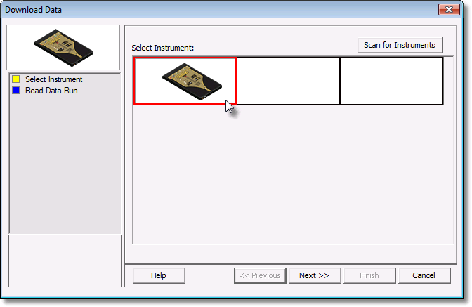
| 4) | Click the Next command button. |
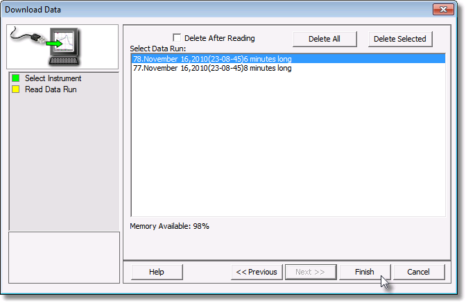
| 5) | Select the desired data run and then click the Finish command button to complete the wizard and read the data run from the M.O.L.E. Profiler. |
|
This step of the wizard allows the user to remove a selected data run from the M.O.L.E. Profiler by either selecting the Delete After Reading check box or selecting the Delete command button and removing it before downloading. This feature is not available for the SuperM.O.L.E.™ Gold Thermal Profiler as it does not have the ability to store more than one data run. |
|
The software allows the ability to download multiple data runs at one time. For consecutive data runs, click the first data run in the list, press and hold down the SHIFT key, and then click the last data run in the list. For data runs that are not consecutive, press and hold down the CTRL key, and then click each data run that you want to import. |
| 6) | When the data run has been downloaded, the software prompts the user to specify new file name (*.XMG). |
|
If a data run (*.XMG) is saved in a different Environment Folder other than the currently selected, the software automatically activates the new Environment Folder. This process does not delete any data run files in the previously set Environment Folder and can be quickly accessed using the Recent Environment Folders on the File menu. |
I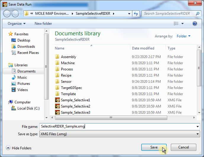
| 7) | When finished, click the Save command button to complete the process. The information is automatically saved in the data run file (.XMG). |
Step 5: Interpreting the Data
Mini Fluxometer Data:
“Good” flux spray patterns are consistent and fully shaped. "Bad" flux patterns are missing, mis-aligned, insufficient, excessive, inconsistent are highlighted by variation.
V-Gauge Test Mesh Measurements:
Purge (Click to zoom): |
|
|
|
Dot Size (Click to zoom): |
|
|
|
Overspray (Click to zoom): |
|
|
|
Y-Axis (Click to zoom): |
|
|
|
X-Axis (Click to zoom): |
|
|
|
UP Test Mesh Measurement:
Uniform Pattern: |
|
|
|
Selective Solder:
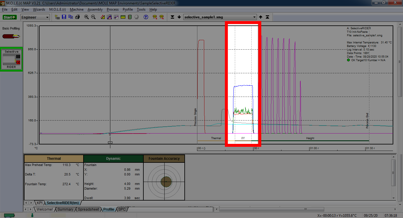
Select the Profile page and then the SelectiveRIDER® Data Table.
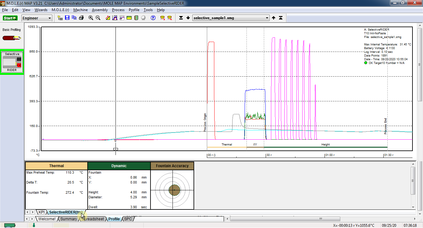
All the respective measures happen automatically. If not, the Process End and X/Y zone boundaries may need to be adjusted.
|
If the Process Origin does not start at the first peak (Channel 1) or did not achieve the minimum required temperature threshold that indicates the solder did not come into proper contact with the sensor. |
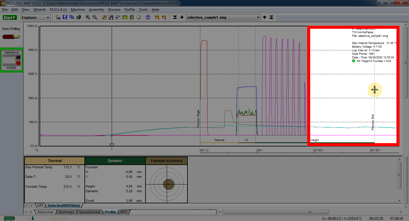
To adjust the Process End:
| 1) | Position the mouse pointer over the Process End (vertical line). |
| 2) | When the mouse pointer becomes a |
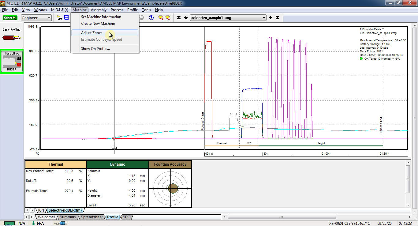
To adjust zones:
| 1) | One the Machine menu, click Adjust Zones to activate. A check mark appears to the left of the command indicating the software is in Adjust Zones mode. |
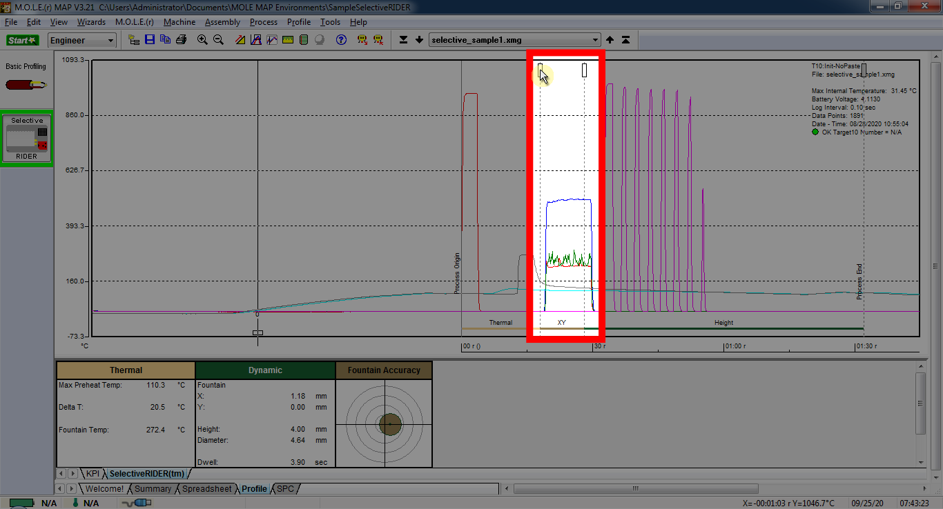
| 2) | Position the mouse pointer over the left X/Y zone boundary line. |
| 3) | Click and hold the left mouse button to drag it left or right releasing the mouse button when the zone line is at the desired location and repeat for the right zone boundary line. The X/Y zone boundaries should be placed just inside the rising/falling edges of the peaks that lay between Process Origin spike and the Height sensor spikes. |
|
If the solder does not contact the Dynamic X/Y Sensor, the contact plateaus will be at room temperature indicating no contact. |
| 4) | Lock the new zone settings by selecting the Adjust Zones command again. This removes the check mark next to the command indicating the software is out of the Adjust Zones mode. |
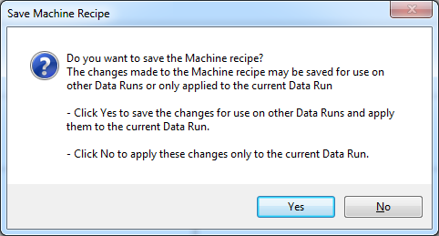
|
The software prompts the user to save the changes to be used on other data runs. This is useful when downloading new data runs so the user can apply the saved Machine recipe to the next data run.
|