Step 1 - Battery Removal
| 1) | Remove the bottom and top cover using a Phillips screw driver to loosen the 2-56 x 3/16 screws (ECD Item: H00-1003-10). |
| 2) | Carefully turn the M.O.L.E. Thermal Profiler over and remove the top cover. |
|
Be careful not to pull to hard as the overlay label may stick to the display. |
| 3) | Disconnect the battery (ECD ITEM: F30-0060-00). |
Step 2 - Display Replacement
| 1) | From the bottom side, carefully open the locks on the J1 & J2 connectors on the main pcb assembly by pressing them away from the connector housing. |
| 2) | From the top side, remove the Display (ECD Item: Y25-0031-00) and Main board display support (ECD Item: M61-3806-60) by loosening the 2 X 3/16 screws (ECD Item: H05-0056-00). |
| 3) | Connect the display and support to the Main PCB assembly. |
✓Make sure the locks on the J1 & J2 connectors on the bottom side of the Main PCB assembly are open. If not carefully open by pressing them away from the connector housing.
✓From the top side, insert the 8 position flex interface cable through the small through slot in the Main PCB assembly and the 45 position flex interface cable through the large through slot.
✓Carefully flip the assembly over and gently bend the 8 position flex interface cable toward connector J2 and the 45 position flex interface cable toward the J1 connector.
✓Carefully insert the 8 position flex interface cable into J2 connector and the 45 position flex interface cable until they are fully seated.
✓Keeping slight pressure on the flex cable, slide the lock of the J2 connectors back in place by carefully pressing it toward the connector housing. repeat for the J1 connector.
|
To help determine if the flex cables are fully seated, each has a white stripe that will no longer be seen if they are in place. |
| 4) | Secure the Main PCB assembly and Main board display support to the frame supports the with four screws, 2 x 3/16. |
|
Snug the screws in place as damage can occur to the frame supports if they are over tightened. |
Step 3 - Battery Installation
| 1) | Connect the Battery connector into the J5 connector on the Main PCB assembly. Coil excess wire and in the Frame support. |
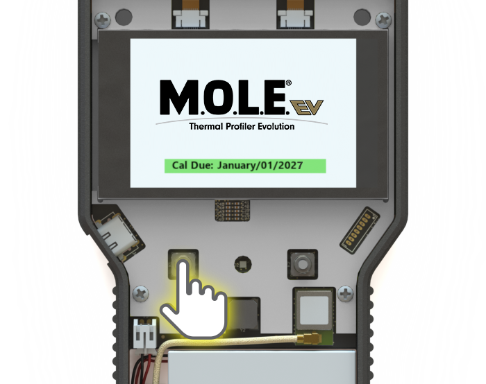
| 2) | Confirm the Display is working. |
✓Press and hold the ON/OFF button.
✓If the Display does not work please contact ECD Support.
| 3) | Secure the Top and Bottom covers to the Frame. |
✓Insert the Frame in the Bottom cover.
✓Remove the clear protective liner from the Display. With a dust-free cloth, clean the Display to remove any finger prints/smudges and debris.
✓Confirm the Display is properly seated in the Support and the Battery wires are within the Frame support.
✓Place the Top cover on the Frame and secure the covers to the Frame with the 2-56 x 3/16 screws.
_zoom20.png)
_zoom40.png)
_zoom40.png)
.png)
_zoom30.png)
_zoom30.png)
_zoom30.png)
_zoom50.png)
_zoom50.png)
_zoom60.png)
_zoom50.png)
_zoom60.png)
_zoom50.png)

_zoom50.png)
_zoom30.png)
_zoom50.png)
_zoom50.png)
_zoom50.png)
_zoom50.png)