The following section guides the user through first time use initial setup requirements for smooth and consistent interactivity between M.O.L.E. and software.
.png)
Profiler Setup: Configure the M.O.L.E.
This Wizard guides the user through a typical process on how to configure a M.O.L.E. to collect data profiles.
|
The BakeWATCH® Kill Step Calculator software is only compatible with ECD SuperM.O.L.E.™ Gold 2 (6-Channel Model) & V-M.O.L.E.™ (3-Channel Model) Thermal Profilers. |
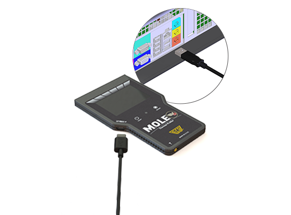
To configure a M.O.L.E.:
| 1) | Connect the M.O.L.E. Thermal Profiler to the computer. |
|
BakeWATCH® Kill Step Calculator software can only communicate with one M.O.L.E. Thermal Profiler at a time. If two are connected to a computer, disconnect the M.O.L.E. that is not being used. Additionally, it is recommended that ECD M.O.L.E.® MAP software and BakeWATCH® Kill Step Calculator are not be used at the same time. If M.O.L.E.® MAP software is running, please close before proceeding. |
| 2) | On the M.O.L.E. menu, click Configure and the dialog appears. |
.png)
|
The Status tab on the Configure dialog box also allows the user to be able to view the current configuration settings stored in the M.O.L.E. Thermal Profiler. This is useful to confirm if the current settings need to be changed or to confirm any settings after they have been changed.
|
.png)
| 3) | Set the M.O.L.E.® name. |
.png)
| 4) | Set the recording Log interval. This is the time between each data point measured by the M.O.L.E. |
|
A 1 second setting is the most common log interval for M.O.L.E. Thermal Profiler. |
.png)
| 5) | Select or clear the Synchronize the M.O.L.E. clock to PC clock check box. When checked, sends the PC's current date and time to the M.O.L.E. |
.png)
| 6) | Change/Adjust the Wait time before M.O.L.E. communication (milliseconds). |
|
Advanced use only: This configuration is used when a very fast computer tries to read information from the M.O.L.E. to quickly, and the M.O.L.E. is not fast to respond. |
.png)
| 7) | When finished, click the OK command button to send current configuration to M.O.L.E. and closes the dialog box. |
Profiler Set-up: Data Collection
|
Never permit the M.O.L.E. to exceed the absolute maximum warrantied internal temperature, as permanent damage may result. The warranty will not cover damage caused by exceeding the maximum specified internal temperature. |
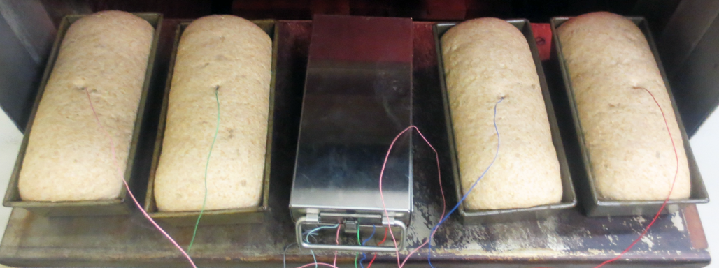
| 1) | Instrument the 6 individual dough pieces laterally across the tunnel oven belt (or high, mid and bottom racks in a shelf oven (rotating or otherwise). |
|
|
.png)
|
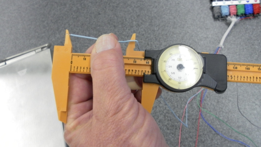
The key to thermocouple placement is measurement. Best practices calls for dough center insertion, so pre-measure ½ depth (or radius if going in horizontally from the side), give the thermocouple (T/C) an elbow bend and insert up to the bend. Also, pinch the dough at the wire exit to prevent outgassing there. Strain-relief T/C wires with other dough pieces and wind up the excess inside the thermal barrier.
|
| 2) | Press the M.O.L.E. "ON" button. |
| 3) | Place the M.O.L.E. in the appropriate Thermal Barrier and press the "Record" button. |
| 4) | Close the Thermal Barrier making sure the sensor wire does not get pinched. |
| 5) | Pass the thermally protected M.O.L.E. through the process. Dependent upon oven entrance access, return the now-instrumented pan strap or tray onto the conveyor. |
|
As always, mind your stop watch and remain in the oven’s vicinity for retrieval. Plan where you’ll stand. A wheeled cart is very handy for rigging and retrieval! |
| 6) | As the M.O.L.E. emerge from the process, remove the sensors from the test product and lay the profile rig on a wheeled cart, table or flat surface. |
|
When retrieving the M.O.L.E. and test product use caution as it may be warm. |
| 7) | Open the Thermal barrier and if the Record button is still flashing this means the M.O.L.E. is still logging and it should be stopped. |
| 8) | Remove the M.O.L.E. from the Thermal Barrier and wait a few minutes for the M.O.L.E. to cool. Handle it carefully, as the case may still be warm. |
| 9) | Disconnect M.O.L.E. from the thermocouples and place it near the computer that has BakeWATCH® Kill Step Calculator software installed on it. |
|
If you remove the thermocouple sensors before the M.O.L.E. has stopped collecting data, it may cause the data to become distorted. |
Kill Step Report Set-up, Profiles Management & Report Generation
Step 1: Kill Step Report Setup
| 1) | On the File menu, click New. and the Kill Step Report setup is displayed. |
.png)
| 2) | Connect your M.O.L.E. to the computer. |
|
Software automatically detects when a M.O.L.E. is connected to a computer. The status is displayed in the Status bar.
|
.png)
.png)
| 3) | Select your food variety from the drop down box. |
.png)
| 4) | Save the New Report by selecting the browse button and navigating to a location where the Kill Step Report files (.KILL) are to be saved. |
|
When saving files it is recommended to have them in a consistent location and appropriately name the folder/file per variety, oven line and other pertinent data in a consistent way. |
.png)
| 5) | After providing a new file name select the Save command button. |
|
Software allows you to replace existing Kill Step Report files. This will however, destroy the data in the existing Report file. |
| 6) | Select the Next command button. |
.png)
Step 2: Profile(s) Management
| 1) | Select a check box next to at least one M.O.L.E. profile and then the Download button to continue. |
|
The software allows the ability to download multiple data runs at one time. Click the check box next to each data run that you want to download. |
.png)
.png)
|
This activity incrementally adds dough thermocouple channel data to what becomes a valid Kill Step Report. |
| 2) | The profile data is then loaded into the profile data management window where data from the downloaded profiles is accumulated. |
|
Reference profiles are displayed for all profiles currently downloaded to this Kill Step file. The active Kill Step File and Food Variety are shown In the profile rows, channel color sequence repeats (1-6 CakeOMETER™ | SuperM.O.L.E.™ Gold 2 or 1-3 if V-M.O.L.E.™), and individual channel D-Reduction and Max-Temp validation data is reported. |
.png)
|
AIB International's Kill Step Protocol for most product varieties calls for a total of 30 channels of data (6 individual dough pieces profiled 5 times in a given oven). Please reference the AIB website for details contained within their official Procedures documentation. Link: https://www.aibinternational.com/inspections-consulting/baking/kill-step-validation/ |
| 3) | If more profiles are needed, select the Add Profiles command button to reach the required number of valid channel profile rows. Monitor current channel count in the Progress Counter. As the count progresses, the background gradually becomes green as the value reaches 30 channels of profile data. |
Step 3: Report Generation:
| 1) | When there is enough temperature profiles for a report, select Generate Report button and the current report is displayed. |
.png)
| 2) | Select the Print button to continue and the Print Management window is displayed. |
.png)
| 3) | Select the Print button to continue or Close to not print the Kill Step Report. |
.png)
Congratulations, you've completed your first Kill Step File Report towards FSMA Compliance. Store both hard and soft copies wisely for future audit protection.